This is a brain-dump inspired by a thread on twitter about correct™ dither in sRGB, meaning, to choose the dither pattern in such a way as to preserve the physical brightness of the original pixels. This is in principle a solved problem, but the devil is in the details that are easily overlooked, especially when dithering to only a few quantization levels.
So, this topic came up on twitter:
I had previously spent some time to wrap my head around this exact problem, so I shot from the hip with some pseudo code that I used in Space Glider on Shadertoy. Code postings on twitter are never a good idea, so here is a cleaned up version wrapped up in a proper function:
vec3 oetf( vec3 ); // = pow( .4545 ) (*) vec3 eotf( vec3 ); // = pow( 2.2 ) (*) vec3 dither( vec3 linear_color, vec3 noise, float quant ) { vec3 c0 = floor( oetf( linear_color ) / quant ) * quant; vec3 c1 = c0 + quant; vec3 discr = mix( eotf( c0 ), eotf( c1 ), noise ); return mix( c0, c1, lessThan( discr, linear_color ) ); } |
How the code works
The linear_color is the value that is going to be written out to the render target. This is the value to be dithered and is supposed to be in linear RGB. The noise argument can be any uniform noise in the range 0 to 1 (preferably some form of blue noise, or it could be an ordered Bayer-pattern). Lastly, the quant argument is the quantization interval, which is “one over the number of levels minus one”; for example: 1/255 for quantization to 256 levels, or 1/5 (= 51/255) to emulate the palette of web-safe colors (6 levels). The free function oetf is used here to stand for an arbitrary opto-electronic transfer function, which for sRGB is nothing more than the good old gamma curve (marked with an asterisk, because you should also not neglect the linear segment if you output for sRGB).
EDIT: In a related blog post, I explain how the gamma curve is really → nothing more than a µ‑law for pixels.
Here is how the dither function works: It first computes the quantized lower and upper bounds, c0 and c1, that bracket the input value. The output is then selected as either c0 or c1 based on a comparison of the input against a discriminant, discr. The salient point is that this comparison is performed in linear space!
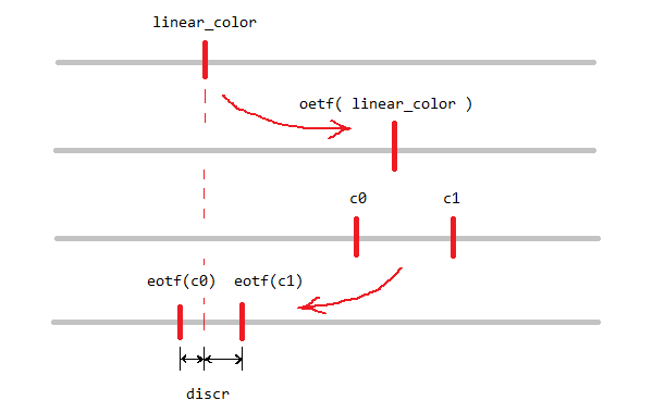
So why is it necessary to compute the discriminant in linear space? Because what matters is physical brightness, which is linear in the number of pixels (at least it should be, on a sane display), but it is not in general linear in the RGB value ifself.
Why the code works
To illustrate further lets continue with the web palette example where there are 6 quantization levels. The following table shows how these 6 levels should map to physical luminance, according to the sRGB-standard:
| value (PERCENT) |
value (8 bit) |
Value (HEX) |
luminance (cD per sq meter) |
example |
|---|---|---|---|---|
| 0% | 0 | #00 |
0 | |
| 20% | 51 | #33 |
3.31 | |
| 40% | 102 | #66 |
13.3 | |
| 60% | 153 | #99 |
31.9 | |
| 80% | 204 | #CC |
60.4 | |
| 100% | 255 | #FF |
80 |
The luminance values here were calculated by following the sRGB transfer function and under the assumption of the standard 80 cd/m² display brightness. Now consider for example that we want to match the luminance of the #33 grey value (3.31 cd/m²) with a dither pattern. According to table we should choose a 25% pattern when using the #66 pixels (3.31 into 13.3), a 10% pattern for the #99 pixels (3.31 into 31.9), a 5.4% pattern for the #CC pixels (3.31 into 60.4) or a 4.1% pattern for the #FF pixels (3.31 into 80). This has been realized in the following image:

All tiles in this image should appear approximately with the same brightness. They may not match perfectly on your display, but they should do at least ok. Make sure the image is viewed at its original size. To minimize resizing errors I have included a 2× version for retina displays that should get automatically selected on MacBooks and the like.

In contrast, using the raw RGB value as the basis for the dither pattern as shown above does not produce a matching appearance. In this case I used a 50% pattern with the #66 pixels (20 into 40), a 33% pattern with #99 pixels (20 into 60), a 25% pattern with #CC pixels (20 into 80) and a 20% pattern with #FF pixels (20 into 100). See for yourself how that does not match!
A real world example
As I said in the beginning, I came up with the above dithering code as a side effect of the continued tinkering with Space Glider, as I wanted to have a somewhat faithful rendition of twilight and night situations, and that means that without dithering, the sky gradient would produce very noticable banding, especially so in VR.

To illiustrate, a took a screenshot of a twilight scene, standing in the mountains with the landing lights on. The darkest pixel in this image is #020204, which is somewhere in the lower left corner. With a VR headset on, and with the eyes dark-adapted, the jumps between #02, #03 and #04 are clearly visible and proper dithering is a must.
I will now show how the code shown in the beginning is working as intended by dithering this image to 2, 3, 4, 6 and 8 quantization levels by simply adjusting the quant variable. Again, all images should match physical brightness impression (and again, on the condition that your browser does not mess with the pixels). The noise input used here is just the Shadertoy builtin blue noise texture, but 2 copies were added together at different scales to make it effectively one 16-bit noise texture.


Conclusion
So that’s it as this is only a quick reaction post. To recap, the dithering problem is complicated by the fact that display brightness in linear in the number of pixels, but non-linear in the RGB value. Getting it right matters for the lowest quantization levels, be it either the dark parts of an image with many quantization levels, or if there are only a few quantization levels overall.
Hi,
The IEC 61966–2‑1:1999 Standard does not specify an OETF but only an EOTF, so the OETF in your article is actually an Inverse EOTF. Some more information here: https://www.colour-science.org/posts/srgb-eotf-pure-gamma-22-or-piece-wise-function/
Cheers,
Thomas
Hi Thomas,
thanks for getting involved! Yes, I was first to write
eotf()andeotf_inv(), but I felt thateotf()andoetf()are visually better distinguishable in code. Also screen space is at a premium in the small code sections, so I went for the most concise option. In any case, your link clears it up. Cheers.Pingback: Correct SRGB Dithering – Hacker News Robot
I’ve just spend two weeks trying to come up with a proper dithering for saving to linear R11G11B10F format, and I’ve kinda given up on it, because with floating-point values you encounter so many additional difficulties, it just didn’t seem worth the hassle. The only thing I got out of it was to notice burn-in on the OLED screen. But your post gave insight on how to distribute the RNG correctly to the physical luminance scale for the final sRGB output!
Why does it always have to be this complicated? Like, it’s probably very hard in the average game for anyone to notice between sRGB or linear dithering. And what makes it even worse: Many games use no dithering at all! You straight-up see the banding. Witcher 3, ArmA 3, just to name a few. But I want to do it correctly, so now it’s time to update it…
Hi Mangudai,
thanks for your thoughts!
For the purpose of dithering, the non-linearity introduced by the floating point format should be handled in the same way as the non-linearity of the sRGB encoding.
You need to write something akin to an “FPOTD” (floating-point-optical-transfer-function) and its inverse. The function is to answer the question, how much physical brightness the individual code points of the fp-format map to. If you do +1 in the fp-format, how much more brightness is it going to gain on the display? Where on the physical brightness level are the next and previous code points (the ones to dither between) located? This would be a piecewise linear function approximating an exponential function.
The usual FP behavior: a linear mantissa ramp until the exponent increases by one, then another mantissa ramp twice as steep, and so on.
Since the fp-format itself is linear, you wouldn’t need to worry about sRGB on top of it, just the fp nonlinearity.
Does that make sense?
Hey, so one more thought, i forgot to add: The usual dither algorithms go with a noise span of 2, while in your algorithm it’s just the two adjacent colors ( span 1). I tested your approach vs the shadertoy implementation here: https://www.shadertoy.com/view/NssBRX
And i must say, your’s looks much better except for the noise discontinuities on moving noise. Because then the interval of 1 creates areas of high noise and areas of low noise. I ask myself if it would be possible to somehow adapt the interval to e.g. 2, but involving 4 colors already creates issues, because there isn’t a unique solution. I’m currently building an interpolation, but it’s getting too late and i need to finish the comment. Hopefully it works out!
I think, the way forward with a broader dither pattern would be thus:
Take the set of neighboring code points that you want to dither between. In the original article there only was and
and  , but you can take any number you like
  and so on.
Map these values back to the linear scale. In general they will no longer be spaced uniformly.
Make interpolation weights, so that for each position of the discriminator, you have weights for and so on such that their linear combination gives the expected brightness.
Then draw a random sample from and so on with probabilities proportional to the interpolation weights.
Does that make sense?
Heyo, one last comment! I’ve thought about distributing the noise a bit more evenly, but it’s not as easy as thought. I explicitly have to quantize adjacent colors too and it quickly gets very noisy. If you want to take a look at the approach, I’ve posted it here: https://www.shadertoy.com/view/t3BXWW
Looks as if this it is a correct implementation of the above idea.
See my comment on shadertoy!
Now the question is open if that particular choice of interpolation weights is in any way good, or ‘optimal’ (for any measure of ‘optimal’). I think one such optimality criterion could be that the variance of the resulting dither is kept constant.